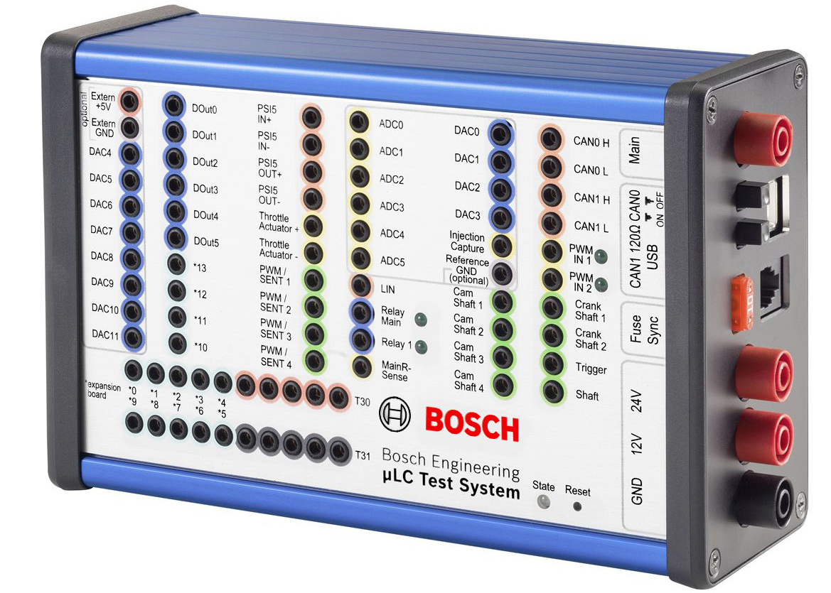
The new and modern hardware-in-the-loop test system µLC Test System is suitable for mobile application, measuring a compact 17 x 11 x 6 cm. Initial test setup typically takes under ten minutes, since the system allows for a simple test setup.
It is a compact open-loop test system for quality assurance of control unit development and combines the simulation of all typical automotive sensors and communication protocols in one unit. Its interface is user-friendly and enables an easy operation and evaluation.
The µLC Test System is especially used for automotive control units with typical interfaces for sensors and bus systems such as analog/digital inputs and outputs, PWM signals, SENT, CAN, LIN and speed sensors.
Downloads
Features
- User-friendly interface
- Functions can be extended with Expansion Boards
- Prepared for test automation
- Favorable test setup, consuming low space
- Simulation of typical automotive interfaces combined in one unit
Application
Engine Speed Simulation
- Up to 20,000 rpm
- Supported sensors: Hall, inductive, DG23i, TL4953
- Up to 2 crankshafts, up to 4 camshafts
- each is independently configurable
- auxiliary shaft
- -180 to 180° camshaft adjustment
- Oscilloscope trigger signal for easier monitoring
- Error simulation for engine position management EPM
Vehicle Busses
- 2 * CAN, up to 1 MBit/s,
switchable 120 Ohm CAN bus terminator - LIN Master/Slave
- SENT, full J2716 Jan. 2012 standard
4 Outputs, alternative to PWM output
Analog Interfaces
- 8 * 10 bit DAC 0 to 5 V, max. 5 mA
Internal or external supply - 4 * 12 bit DAC 0 to 5 V, max. 5 mA
- 6 * 12 bit ADC 0 to 40 V, GND reference
Digital Interfaces
- 6 * Digital Out, max. 200 mA in total
Output modes: Ground, 12 V, High impedance - 2 * Relays, max. 10 A, separate ECU power supply possible and incl. main relay sensing
- 2 * PWM input, 8 Hz to 20 kHz
- 4 * PWM output, max. 90 mA in total,
0.1 Hz to 20 kHz
Output voltages: 12 V, 5 V, GND - Complex PWM with sub signals, each separately adjustable in frequency, duty cycle and pulse count
Additional Features
- Throttle body simulation
- Cylinder pressure simulation
- Up to 8 cylinders with one device
- Expandable with multiple devices
- USB connection completely galvanic decoupled
- All in- and outputs short-circuit protected and ESD protected
- EMC tested
- Expansion boards for additional HW features
- Multi device support with sync option for engine speed signals
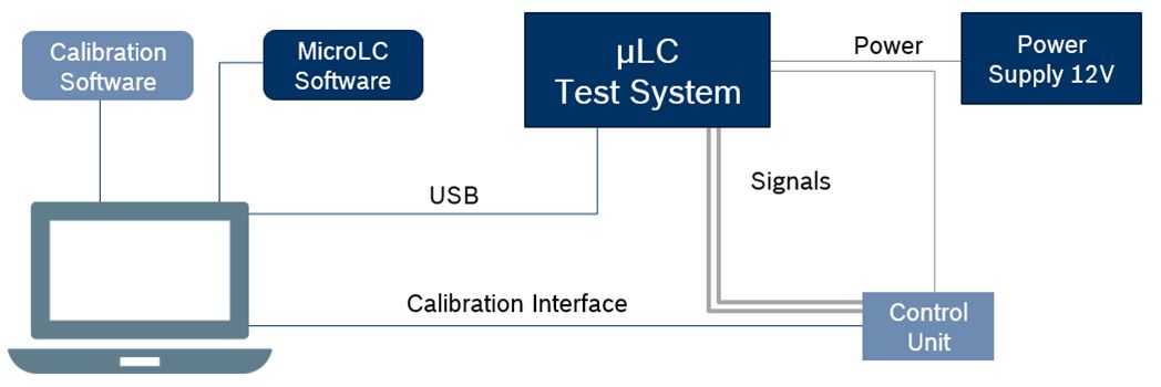
Test Setup

Note: Calculation intensive modules like cylinder pressure simulation can cause a limitation of e.g. the max. engine speed.
Technical Specifications
Operating voltage | 12 V DC |
Current consumption | typ. < 1 A |
ECU voltage | 12 V / 24 V DC |
ECU current | 10 A |
Permissible operation temperature | 0 to 40°C |
Housing material | Aluminum |
Dimensions | 175 x 107 x 61 mm |
Weight | 690 g |

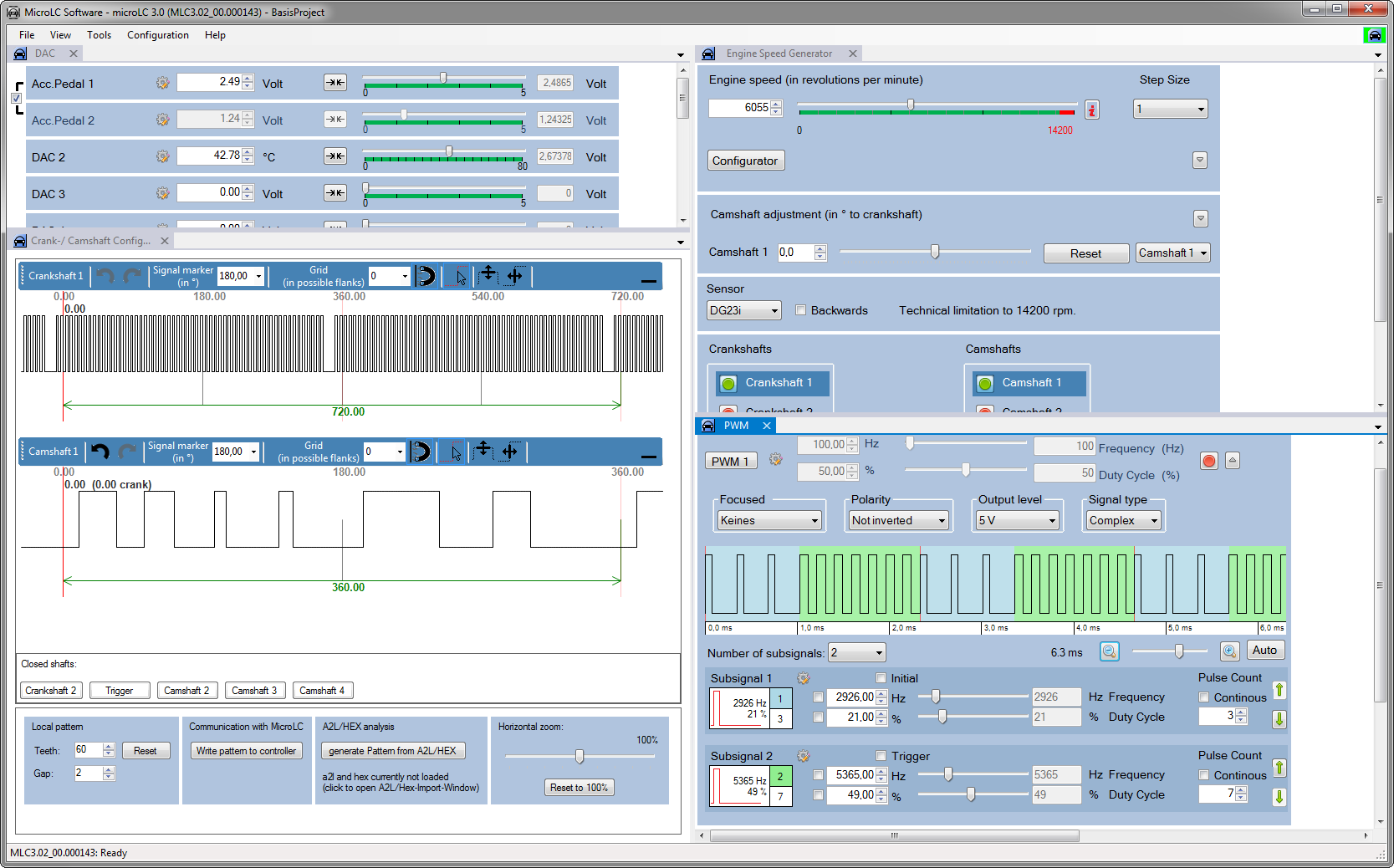
The screenshot shows the MicroLC Software with analog outputs, crank-/ camshaft, RPM and complex PWM.
Update and Support Subscription
- Free in the first year of use, chargeable from the second year
Ordering Information
µLC Test System
Order number: F02U.V02.303-02
Software Options
Update and Support Subscription
Order number: F02U.V02.838-01
Accessories
Expansion Board CAN-FD
Order number: F02U.V03.095-01
Expansion Board Current Loop Interface
Order number: F02U.V02.889-01
Expansion Board Digital Multichannel Pot.
Order number: F02U.V03.129-01
Expansion Board Digital Outputs
Order number: F02U.V02.904-01
Expansion Board FlexIO
Order number: F02U. V03.360-01
Legal Restrictions
The sale of this product in Mexico is prohibited.
Due to embargo restrictions, sale of this product in Russia, Belarus, Iran, Syria, and North Korea is prohibited.
